
Equipment Configuration
Air Velocity Indicator—Any calibrated means of measuring air velocity at the specified rate.
Hot Plate—A guard ring flat plate composed of a test plate, guardring, and bottom plate as follows, each electrically maintained at a constant temperature in the range of human skin temperature [33 to 36°C (91.4 to 98.8°F)].
Test Plate—The test plate portion of the hot plate shall be at least 150 mm (6.0 in.) square and shall be placed at the center of the upper surface of the hot-plate assembly. It shall be made of aluminum or copper and painted a dull black to approximate the emissivity of the human skin. The heating element shall consist of parallel wires, preferably of constantan metal, insulated from, but mounted within 3 mm (0.1 in.) of the upper plate.
Guard Ring—The guard ring bordering the test plate shall be at least 63.5 mm (2.5 in.) in width and shall be of the same thickness, composition, and type of construction as the test plate. It shall be coplanar with the test plate, and shall be separated from it by means of a strip of cork or other suitable insulating material approximately 3-mm (0.1-in.) wide. The guard ring shall be designed to prevent lateral loss of heat from the test plate.
Bottom Plate—The bottom plate shall be of the same thickness, composition, and type of construction as the test plate and guard ring. The bottom plate shall be in a plane parallel to the test plate and guard ring, and at a distance of at least 25 mm (1.0 in.) but not in excess of 75 mm (3.0 in.) beneath them. The purpose of the bottom plate is to prevent a downward loss of heat from the test plate and guard ring.
Temperature Control—Separate control of the temperatures of the three sections of the hot plate (test plate, guard ring, and bottom plate) shall be established by independent adjustments of the heater currents through adjustable transformers, variable impedances, or intermittent heating cycles. Automatic regulation of temperatures is recommended. Use a constant voltage supply, controlled to 61 % to minimize fluctuations in temperature.
Power-Measuring Instruments—One of any of the following instruments shall be used for measuring power: Wattmeter, Watt-hour meter and clock, Voltmeter and ammeter, or Either a voltmeter or an ammeter can be used if the test plate heater resistance at operating temperature is exactly known. These devices shall be operated in accordance with standard practice and shall be calibrated to measure power with an accuracy of 62 %.
Clocks—When heater power is supplied on an intermittent basis, a running-time clock, energized in synchronism with the heater, shall be used to indicate the total time of heating. Another similar clock shall be used to indicate either the total time or the time during which the heater is not energized. The total limit of error of such clocks shall be less than 1 % under service conditions.
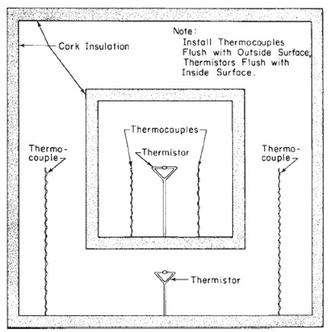
Equipment for Measuring the Several Plate Tempera-Thermocouples—The test plate, guard ring, and bottom plate shall each contain one or more thermocouples made of a junction of wires of copper and constantan, each of B & S Gage No. 30 [0.255 mm (0.01 in.)]. After calibration, these thermocouples shall be positioned within the material of the plates as close to the external plate surfaces as physically possible [1.6 mm (0.06 in.)] to measure the temperatures of the respective surfaces.
Ice Bath, as a reference junction for the thermocouples, or equivalent device. 5.5.3 Potentiometer, accurate within 62.5 μV, to measure the thermocouple emf’s.
Switch—A thermocouple selector switch for separately connecting to each set of thermocouples.
Test Chamber—A chamber to house the hot plate that can be maintained at selected temperatures between 4.5 and 21.1°C (40 to 70°F) with a constancy of 60.5°C (6 2.5°F). The walls of the test chamber shall not be highly reflective, and the wall temperature shall be equal to that of the air in the chamber. The chamber shall be equipped with the following instruments for maintaining the relative humidity at 506 30 % for maintaining the air temperature, and for controlling the air velocity at the approximate rate of 0.1 m/s (0.33 ft/s). The hood for maintaining nearly still air conditions, shown in Fig. 1, is needed.
Relative Humidity Measuring Equipment—Either a wet-and-dry bulb psychrometer or a calibrated humiditysensitive electrical conductor.
Air Temperature Detector—Athermocouple similar to those in the plates is suspended with the measuring junction exposed to the air at a point 500 mm (20.0 in.) above the center of the test plate, inside hood.